Ghostbuster Belt Circuit
Despite being one of the least known parts of the Ghostbuster uniform, the belt circuit is a requirement if you want an accurate costume. There are various versions shown between both movies though the consensus is the board is from a 1970's Sanyo ICC-808D or Minolta Minolcom calculator (same calculator, different branding). These are almost impossible to come by and even if you do find one chances are it won't be completely correct due to variances in the production run.
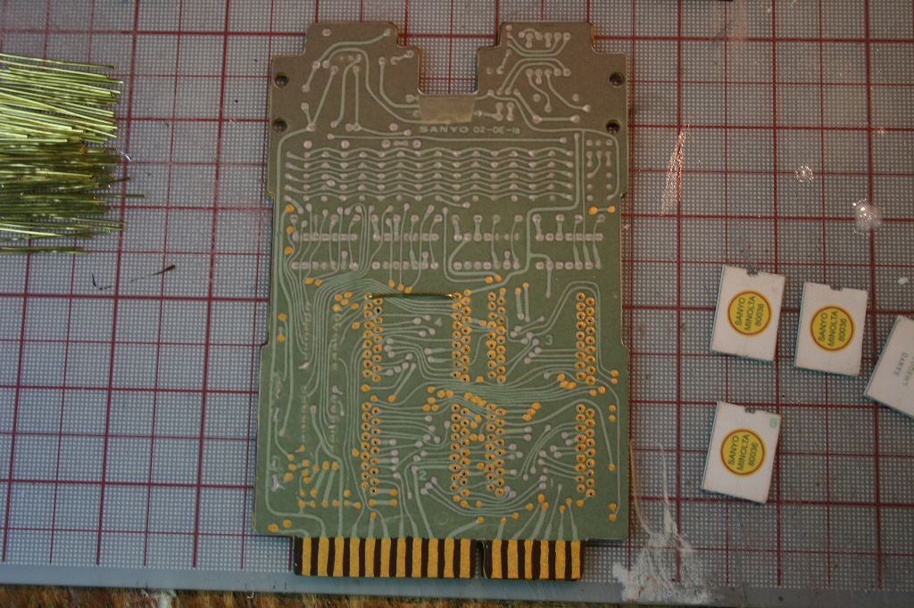
Fortunately the GB community has documented the correct board fairly well (here and to an extent here). A scan of the back and the various chips on it is available (here if you're interested) so it's fairly straight-forward to make a scratchbuilt board.
I started by printing out the PDF on sticker paper and cutting out the board image. I then used that as a template to cut a piece of .08 styrene to shape. The board was then primed and painted.
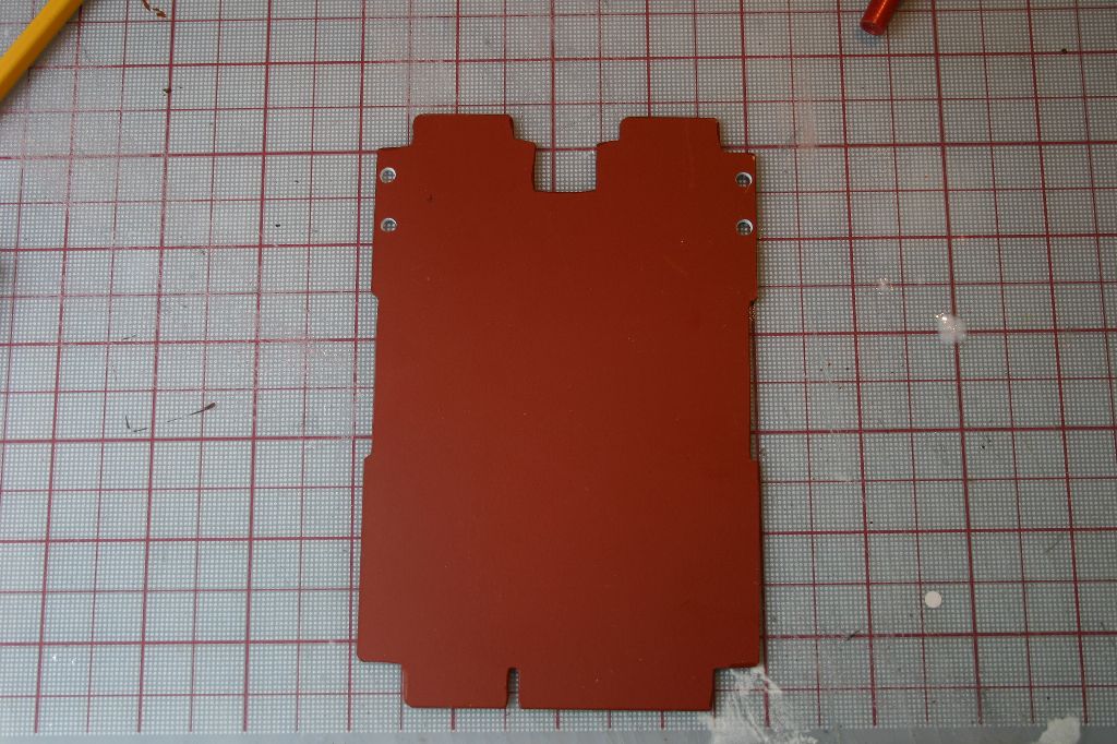
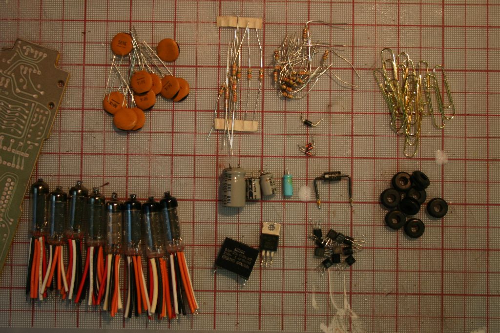
With the board painted I attached the sticker and then collected the rest of the parts needed. I decided to make it as accurate to the actual board as possible, using as many real parts as I could find.

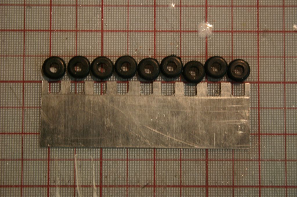
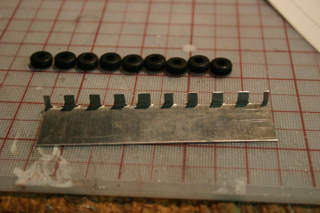
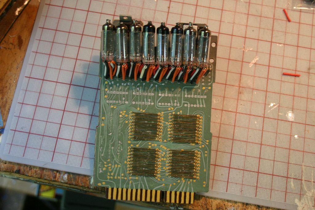
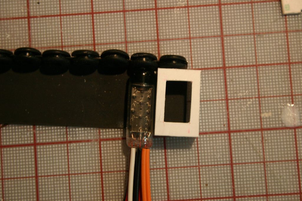
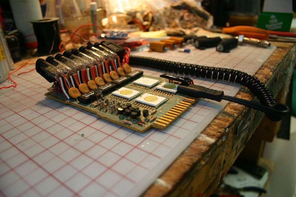
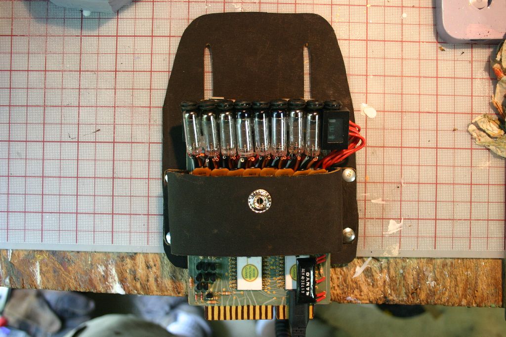
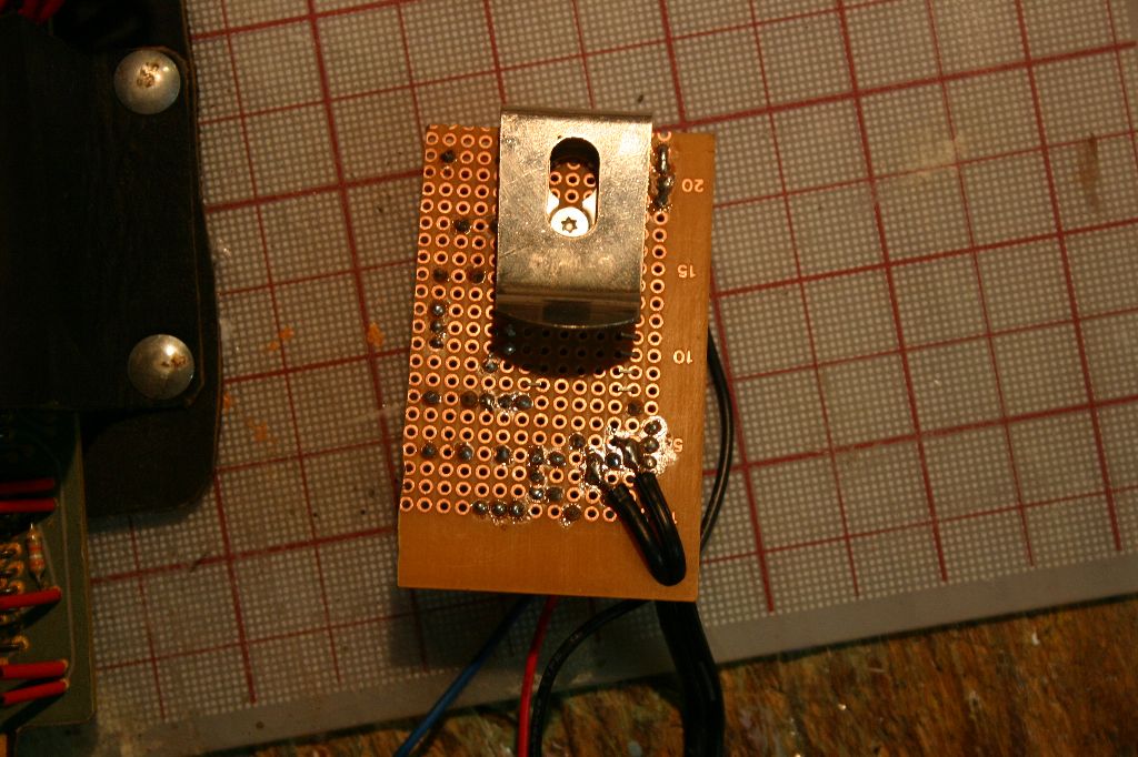
The bracket that holds the nixie tubes is made from aluminum. The PDF has templates for it but in looking at reference pictures I realized that the correct version is actually free-floating, it's only attachment to the board is through the nixie wires. I cut the aluminum with a jewelers saw and bent it in a bench vice. The top was painted flat black (the underside is left unpainted) and rubber grommets are added to hold the nixies. After painting I scratched up the positions where the nixies would go to improve glue adhesion.
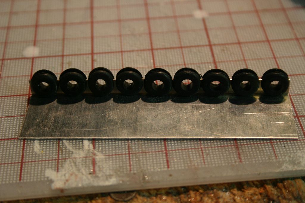
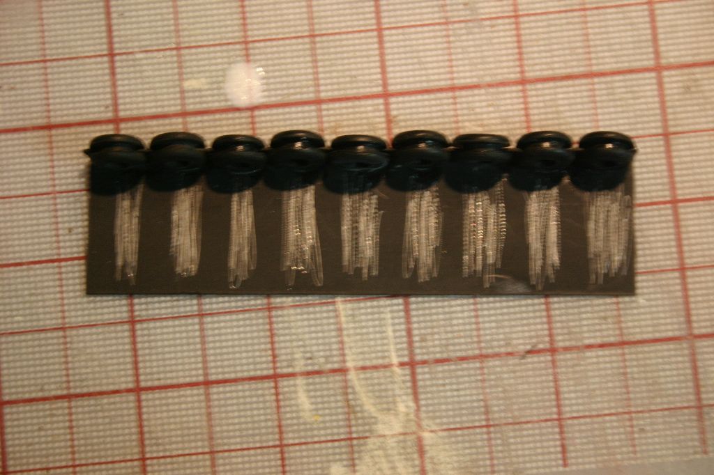
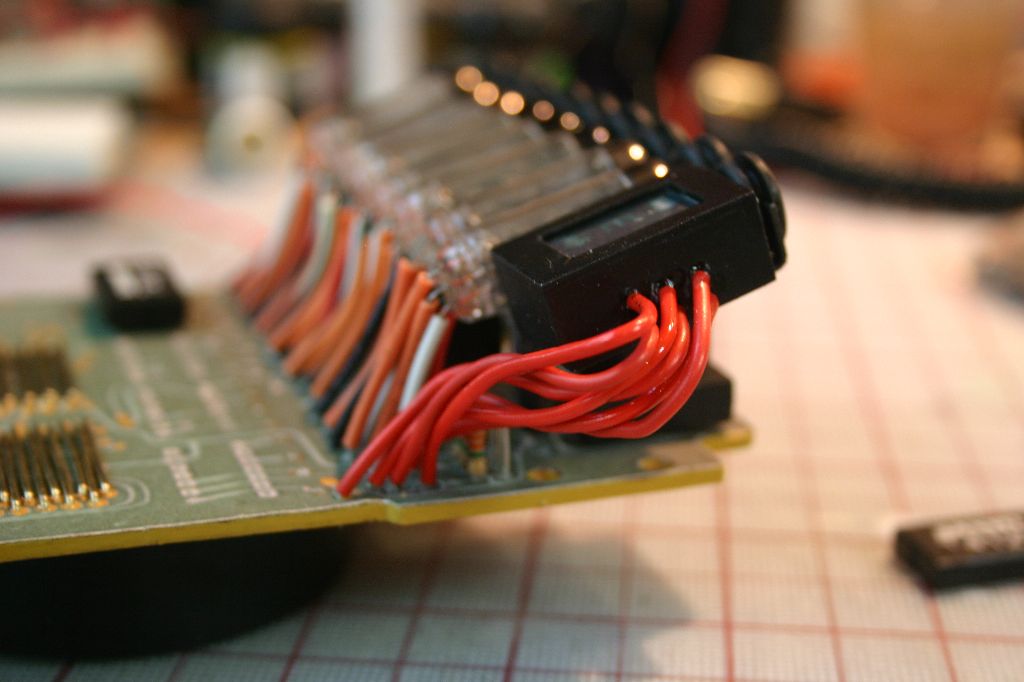
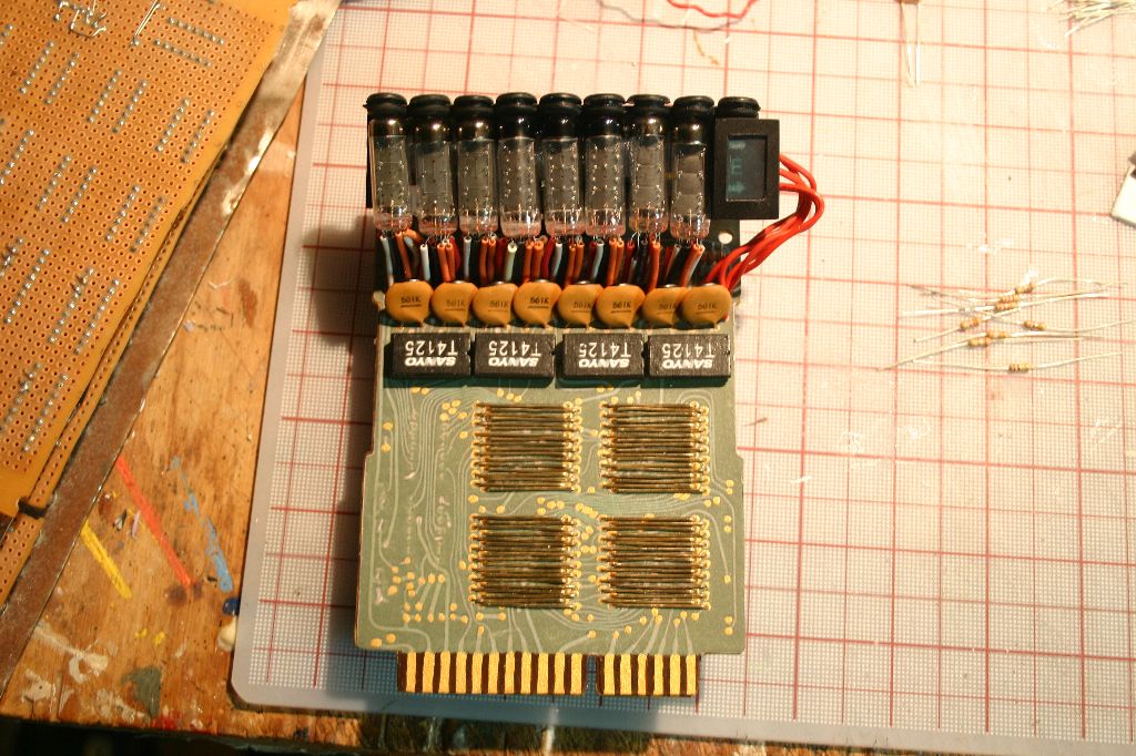
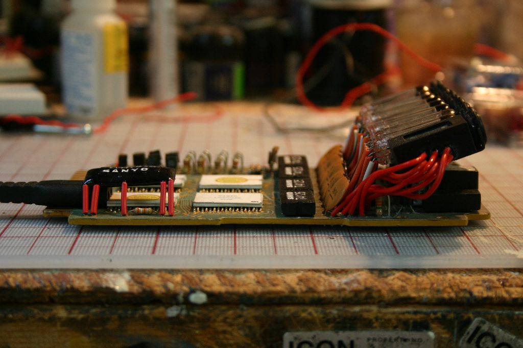
The nixie tubes used in the calculator had 10 leads. The closest ones available to them are IV-9 Numitrons. Though the majority of these only have 9 lead a few of the ones I purchased had 14. I was actually a little annoyed that the IV-9s I ordered weren't all identical, some had an added cross pattern in the center of the digit while others were just a slightly different design. The nixies don't come with any insulation on the wires so this needs to be added. The accurate board had a combination of brown, black, white and red insulation. All the brown wire I had was too small to slide onto the nixie leads so I wound up using orange. The wire insulation I used is actually a little larger than I'd wanted but any smaller and it wasn't possible to get it onto the leads. The sequence on all the tubes is the same, starting with the ground wire going clockwise: Orange, black, white, red, black, red, white, black, orange. For the nixies with 14 leads I cut off 4 and added an extra black between the two red wires.
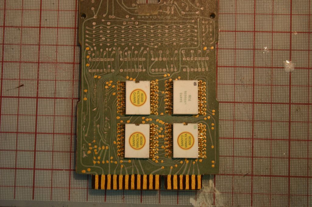
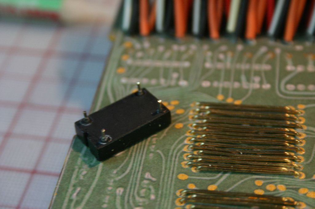
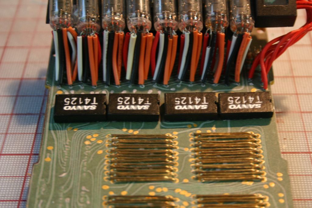
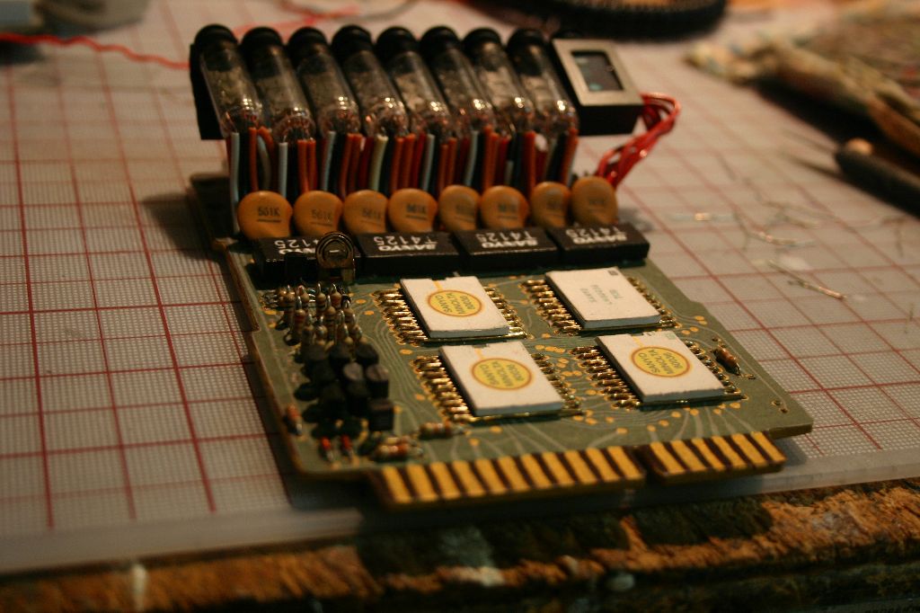
Before I could attach the nixies I had to add the rest of the parts to the board. I went over the board with a gold pen and touched up the "solder points". The four white chips have 18 wires each. To make these I bought a pack of brass paperclips. I got three wires out of each paperclip after straightening them out with a pair of pliers. All the holes were drilled by hand, the wires bent and then glued into place with superglue. The chips were made from .06 styrene and the stickers from the PDF were attached.

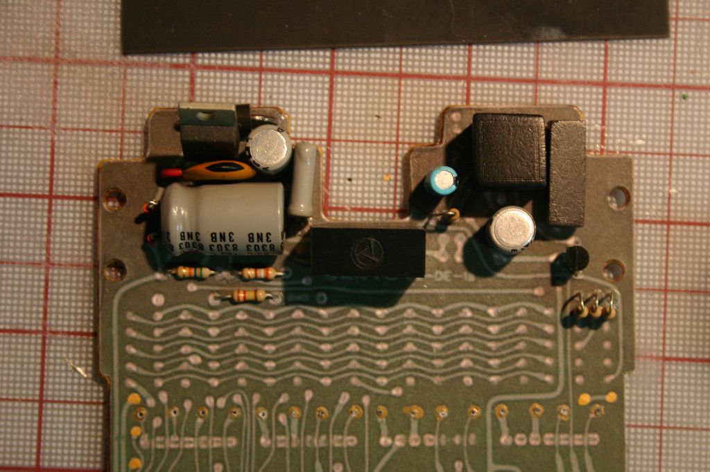
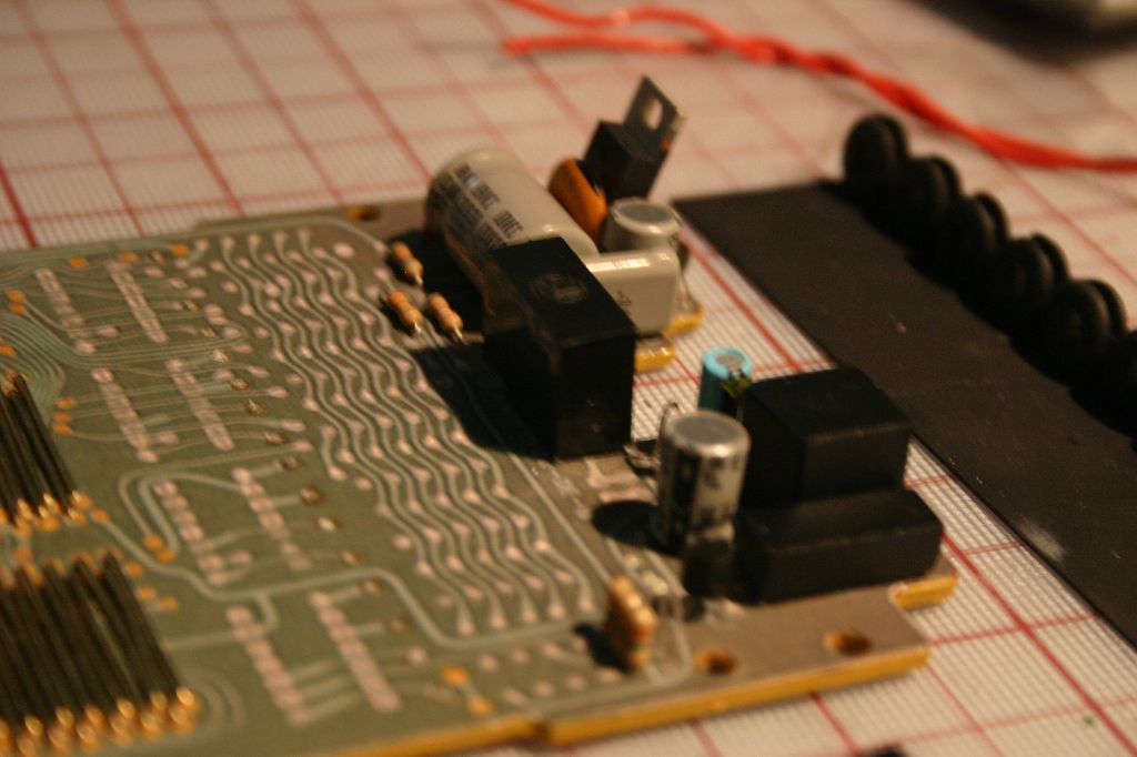
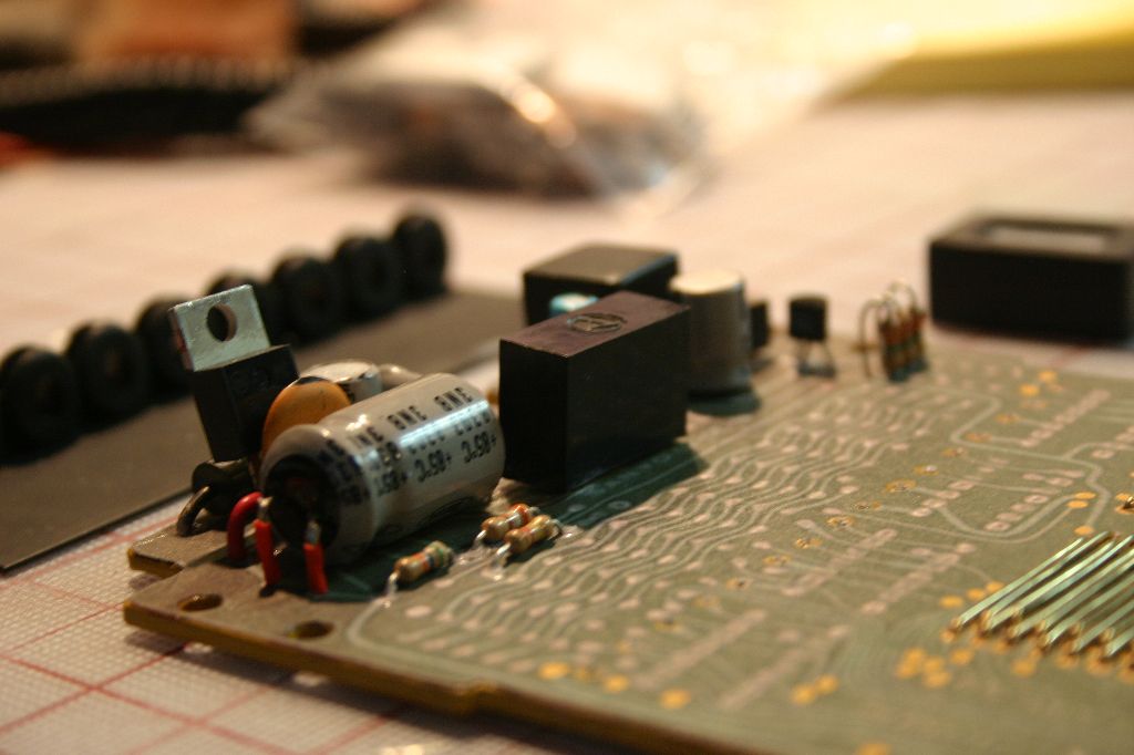
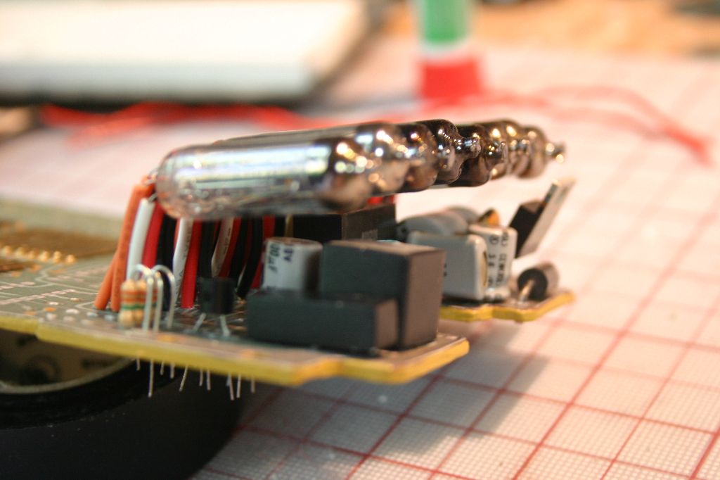
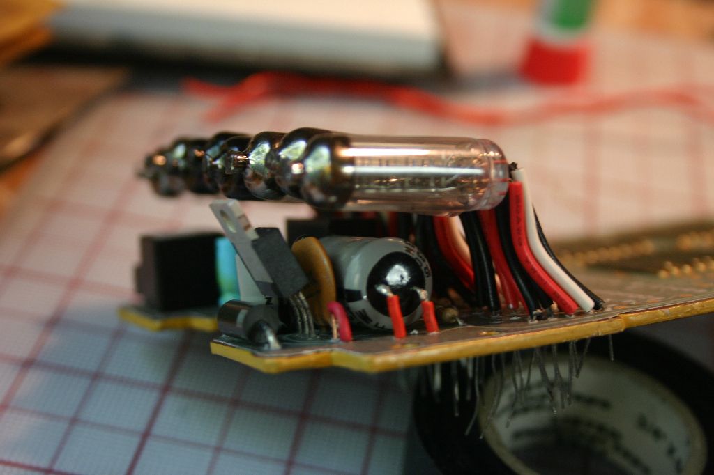
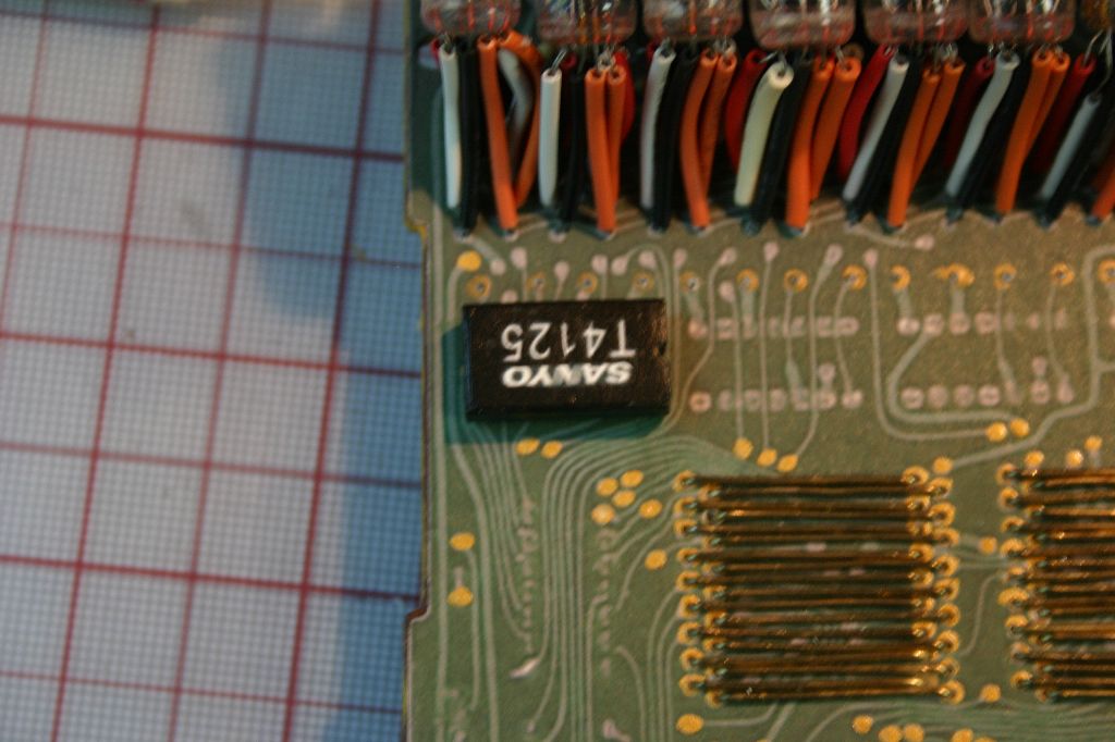
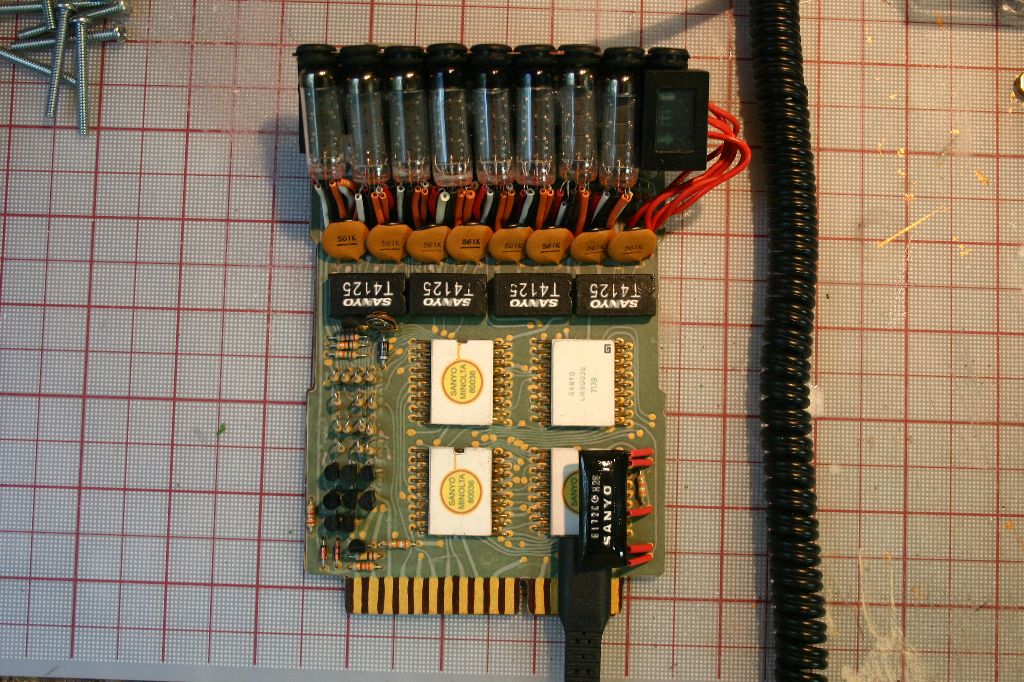
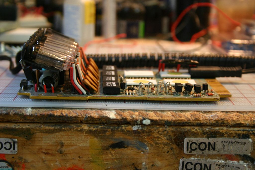
Next up was the stuff behind the nixies. The capacitors, mosfet, transistor, oscillator and one relay were taken out of old electronics while the resistors I had laying around. The relays in the upper right though I had to scratchbuild out of styrene. Everything was pinned through the board and glued in with superglue.
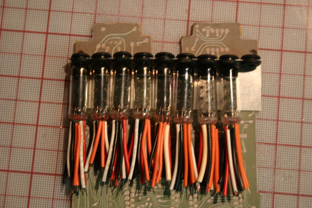
With those bits added I could attach the nixies. After drilling all the holes I positioned one nixie to determine the lengths I needed to trim the insulation to. Once that was figured out I used it as a template to trim the rest then glued them all in.
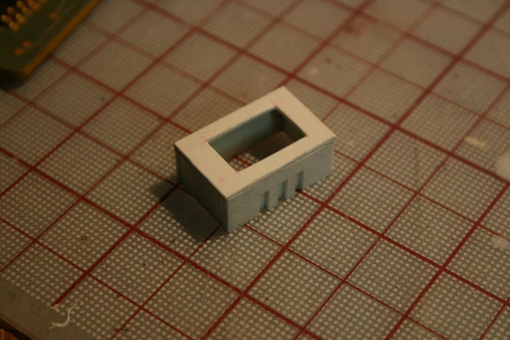
I spent some time positioning the nixies and getting the wires to sit right. I had to figure out what glue to use to attach the bracket to the nixies as metal to glass in a tight space is a tough call. Eventually I settled on high-temp hot glue, it's easy to use, adheres well and dries quickly. I made sure to use high-temp as I didn't want it coming apart on a hot day. At this time I also built the error light box out of styrene. I used some clear plastic for the "window" and then printed out the detail on a clear sticker label. Six red wires go from the error box to the board.


The four black chips on the board were made from a double layer of .08 styrene. I pinned the chips onto the board and glued them from the back. After applying the decals I went back over them with black paint to tie the decal into the plastic better.
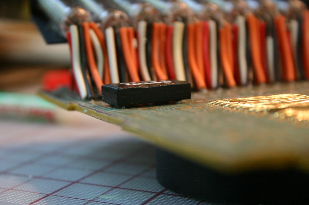
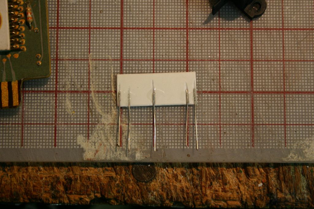
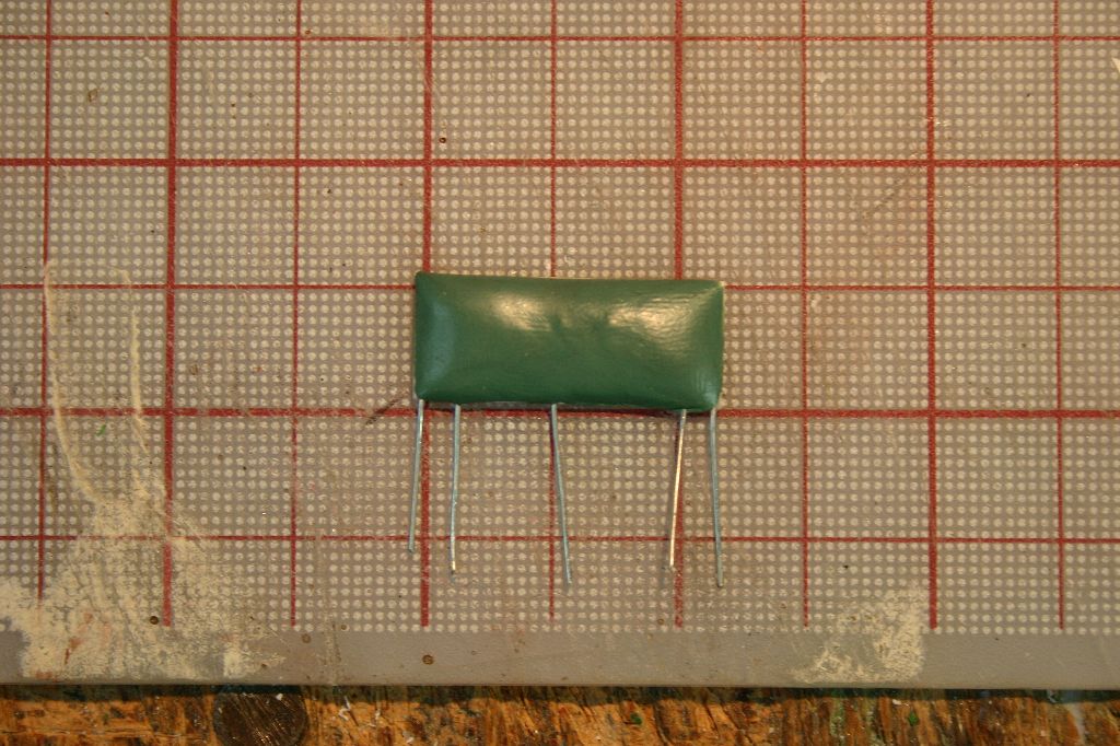
Next up was the various resistors, transistors, capacitors, diodes and potentiometer on the board. The large brown capacitors between the nixie leads and the black chips were the only components I bought other than the nixies. The scan of the actual board is actually the back of the board mirror flipped (and it's not quite the exact board) so it doesn't completely line up with where the components go. I wound up using the gold pen again to lay out solder points then drilled and glued the parts in. I tried to match up the resistor values as much as possible though I couldn't make out all the vertical ones.


The last bit was the black blob thingy (no idea what it is) on the lower right of the board. I glued wire cutoffs to some styrene then used greenstuff putty to build it up.
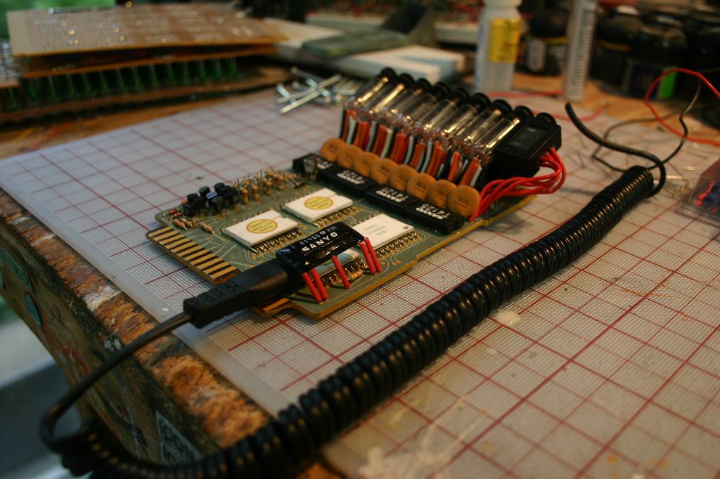
Another decal sticker was added to the black blob part, the red insulation was added and it was glued in. The black coiled wire is actually a recharging cord for a cordless razor. This was pinned and glued to the board and I declared it done.

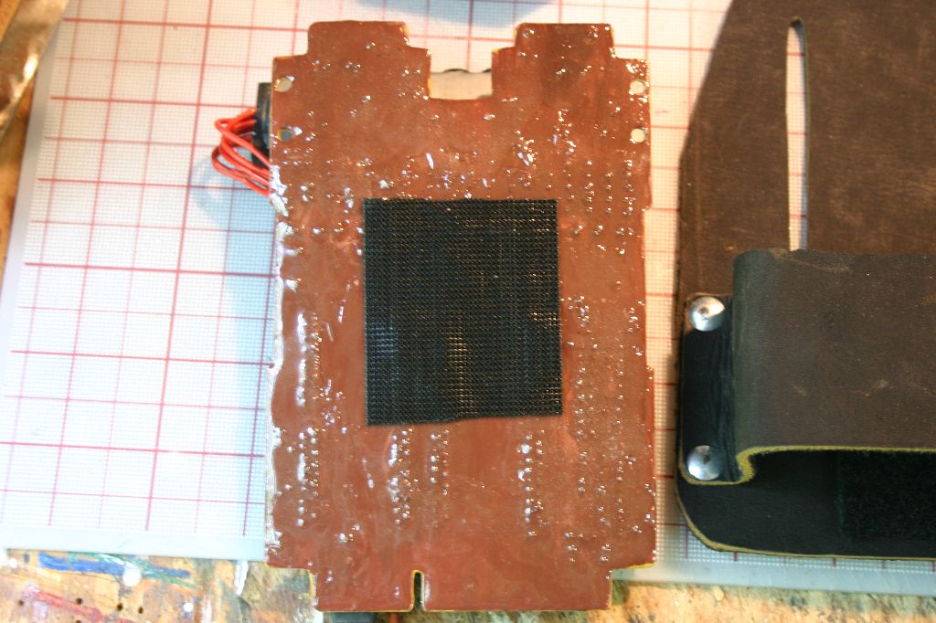
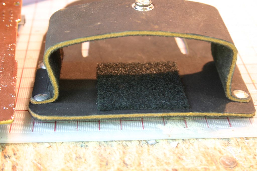
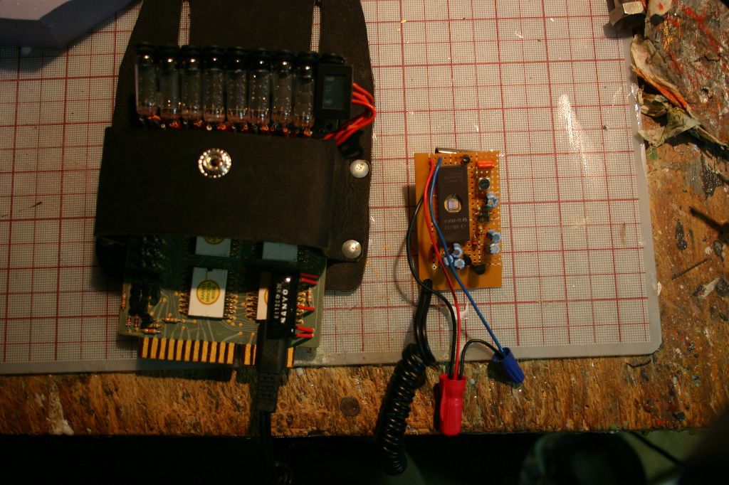
Of course I still needed to make the daughter board and the holster. The holster was relatively simple, some scrap leather from Ebay and some rivets. A bit of industrial velcro secured the circuit board in.
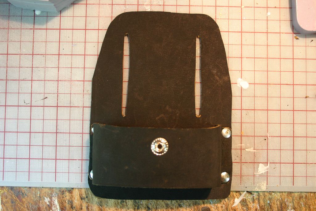
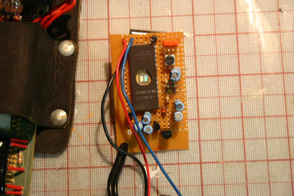
The daughter board was tricky as there are no clear pictures of the GB1 version(I didn't want to do a GB2 version). I wound up making an amalgam of various details that I could make out from the pictures. A tape measure clip screwed to the back and was done.

Tweet
